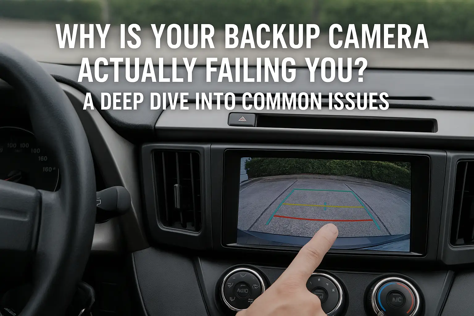
Is your backup camera a source of constant frustration? A flickering, foggy, or completely blank screen transforms a key safety tool into a dangerous distraction, undermining the very reason you have it.
Most backup camera failures stem from three core areas: electrical system integrity1, physical damage or contamination, and software or setting conflicts. Understanding the root cause, from voltage drops to signal interference, is the key to a permanent, reliable fix.
As the founder of VST Tech, I've spent my career obsessing over the reliability of automotive safety systems. A backup camera isn't just a lens and a screen; it's a complete system where every link in the chain—from the power source to the final pixel on your display—must be perfect. I've seen firsthand how a simple issue like a poor ground connection can render a multi-thousand-dollar infotainment system's feature useless. Let's move beyond the surface-level fixes and diagnose these problems like a professional engineer, so you can truly trust the view behind you.
What's Causing Those Annoying Flickers and Lines on Your Screen?
You shift into reverse, and the screen comes alive with a distracting strobe effect or scrolling lines. This visual noise makes it impossible to focus on obstacles, causing hesitation and stress.
This is a classic signal integrity problem. Flickering or lines are caused by "dirty" electrical power or radio frequency (RF) interference corrupting the video signal before it reaches your screen. A simple power filter or a dedicated relay is often the definitive solution.
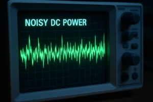
In our labs at VST Tech, we use oscilloscopes to visualize the power going to our cameras. A perfect signal is a flat, stable line of DC voltage. A "noisy" signal is full of spikes and dips. This is what your camera is "seeing" from the car's electrical system, and it's what causes the visual chaos on your screen.
The Physics of a Bad Signal
Most backup cameras transmit an analog video signal (like NTSC or PAL). This signal is sensitive to fluctuations in its power supply. When your engine is running, the alternator is working hard and can introduce small, rapid voltage changes into the car's electrical system. This "alternator whine" can directly interfere with the video feed, creating scrolling lines. A sudden flicker, on the other hand, often points to a momentary, complete loss of connection—a loose wire that's making and breaking contact.
The Professional's Diagnostic Approach
To truly diagnose this, you need a multimeter. Set it to DC voltage and test the power line connected to the camera.
- Engine Off (Accessory Mode): The reading should be a stable ~12V.
- Engine On: The reading should be a stable ~13.5V-14.5V. If you see the numbers jumping around erratically, you have confirmed a noisy power source.
This is where a dedicated power solution becomes essential.
| Solution | How It Works | Best Use Case |
|---|---|---|
| 12V Power Filter | An inline capacitor and inductor that smooths out minor voltage fluctuations. | Fixes most cases of rolling lines or mild, consistent flickering. |
| 12V Relay | Uses the reverse light's signal to trigger a switch, pulling clean, direct power from the battery. | The ultimate fix for severe noise or when tapping power from a pulsed (PWM) taillight circuit. |
Why Are You Getting the Dreaded 'No Signal' Screen?
You put the car in reverse and are met with a black or blue screen, often with the text "No Signal." The camera is completely non-functional, leaving you with a dangerous blind spot.
A "no signal" error indicates a total failure in the power or video transmission chain2. This could be a blown fuse, a completely severed wire, a failed camera unit, or even a software issue in the head unit.
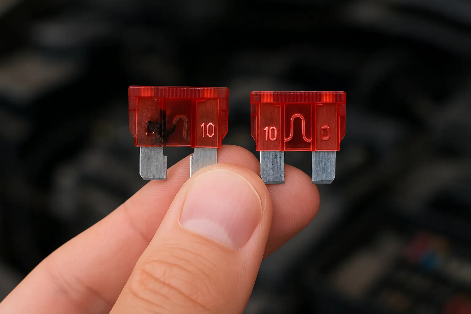
A black screen feels catastrophic, but the fix is often surprisingly simple. The first question I always ask is, "Is the camera getting power, and is the head unit being told to look for its signal?" It's a two-part problem.
Tracing the Entire Electrical Path
Forget just checking the fuse. You need to think about the camera's entire lifeline.
- Power Source: This is often tapped from the reverse light wire. Is that wire providing a consistent 12V when in reverse?
- Ground Connection: This is the most overlooked failure point. A rusty, loose, or poorly chosen ground point is the same as having no power at all. The ground wire must be attached to a clean, unpainted metal point on the car's chassis.
- Video Cable: The RCA or proprietary video cable can be pinched or severed, especially where it passes through the trunk hinge or a rubber grommet.
- Head Unit Trigger: Your infotainment screen needs a signal (usually another 12V wire) to tell it "the car is in reverse, switch to the camera input now." If this trigger signal is missing, the screen will never switch over, even if the camera is powered on.
Complications in Modern Vehicles: The CAN Bus
In many newer cars, the reverse signal isn't a simple 12V wire. Instead, it's a digital message sent over the car's Controller Area Network (CAN bus). If you tap a wire expecting 12V, you might get nothing, or a fluctuating voltage that can't power the camera. In these cases, you need a specific CAN bus3 adapter that listens for the digital "reverse" message and then outputs a clean 12V signal for your camera and trigger wire. This is a common stumbling block for DIY installers on modern vehicles.
Is a Foggy or Blurry Lens Making Your Camera Useless?
The image is hazy, blurry, or looks like it's being viewed through a glass of milk. This is especially bad at night or in the rain, making it impossible to see details.
A blurry image is caused by one of two things: external contamination on the lens, or internal condensation4 due to a failed waterproof seal. Cleaning is the first step, but internal fogging points to a critical hardware failure.
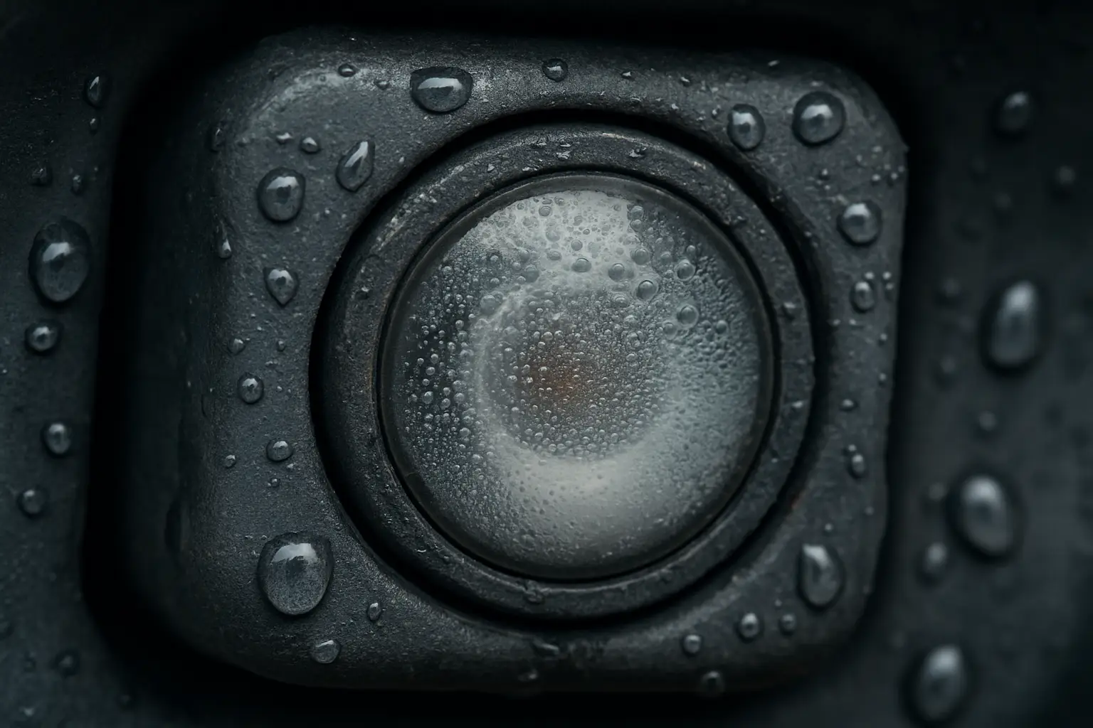
At VST Tech, we subject our cameras to extreme environmental testing. We blast them with high-pressure, high-temperature water jets to ensure their seals hold. Why? Because we know that once moisture gets inside, the camera's life is limited.
The Science of Internal Condensation
This happens when a camera with a poor seal experiences a rapid temperature change. For example, going from a warm garage into a cold rain. The air trapped inside the camera housing cools, and the moisture in that air condenses on the coldest surface—the inside of the lens. Low-quality cameras use cheap rubber gaskets or sealants that crack and fail over time, allowing humid air to enter. Once the moisture is in, it's very difficult to get out.
Understanding IP Ratings: Your Best Defense
When you buy a camera, look for its Ingress Protection (IP) rating. This two-digit code tells you how well it's sealed.
- First Digit (Solids): 6 is the highest, meaning it's completely dust-tight.
- Second Digit (Liquids): This is the crucial one.
- IP67: Can be submerged in 1 meter of water for 30 minutes. (Good)
- IP68: Can be submerged deeper and longer than IP67. (Better)
- IP69K: Can withstand high-pressure, high-temperature spray downs. (The gold standard for external automotive components)
A camera with a failed seal and internal fogging is on borrowed time. The moisture will eventually corrode the delicate electronics. The only real, long-term solution is to replace it with a unit that has a high IP rating.
Are Bad Angles and Crooked Guidelines Making Parking Harder?
Your camera works, but it's aimed at your bumper or the sky. The colorful parking lines are crooked and don't match the actual parking space, making them more of a distraction than a guide.
This is a problem of geometry and calibration. The camera's physical position must be correct before the software-based guidelines can be accurate. It requires both a mechanical adjustment and a software setup.
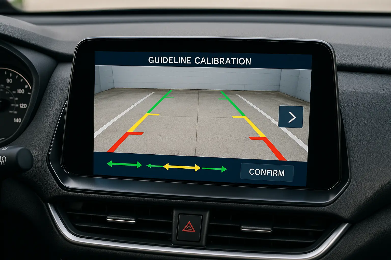
Think of the guidelines as a stencil laid over the camera's image. If the camera (your eye) is looking at the world from a crooked angle, the stencil will be crooked too. We must fix the physical angle first.
Differentiating Guideline Types: Static vs. Active
It's important to know what kind of guidelines you have.
- Static Guidelines: These are a simple, fixed overlay. Their position depends entirely on the camera's physical mounting. You must get the camera perfectly centered and level for them to be accurate.
- Active Guidelines: These lines bend as you turn your steering wheel. This is a much more advanced system. The camera system is integrated with the car's steering angle sensor via the CAN bus. If these lines are inaccurate, it can indicate a calibration issue where the system needs to be "re-taught" what the center steering position is.
The Two-Step Calibration Process
- Mechanical Alignment: Park on level ground. Look at the camera itself. Is it centered on the vehicle? Is it tilted? Use a small plastic shim or loosen its mount to get it perfectly level and aimed so that the very bottom of the screen just shows the edge of your bumper. This provides a crucial point of reference for depth perception.
- Software Calibration: Once the camera is physically correct, go into your head unit's settings. Find the "Guideline Calibration" menu. This will typically display the lines and allow you to adjust their width and position. Use the real lines of a parking space as your reference to align the on-screen guides perfectly. For active systems, this process may also involve turning the wheel lock-to-lock to calibrate the steering angle input.
Conclusie
Resolving backup camera issues requires moving beyond simple fixes to understand the system's electrical, physical, and software foundations. A reliable rear-view is non-negotiable for modern driving safety.
-
Learn how electrical integrity impacts backup camera performance and discover solutions to common issues. ↩
-
Explore the components of the video transmission chain and how they affect camera performance. ↩
-
Learn how the CAN bus system affects backup camera functionality in newer vehicles. ↩
-
Discover the impact of internal condensation on backup camera functionality and how to prevent it. ↩

